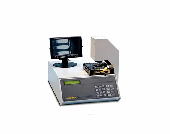
Visual Melting Point Apparatus (MRVIS+)
The Visual Melting Point Apparatus allows the researcher to get an indication of the compound or element’s purity. The entire operations of the melting point apparatus are controlled by the central processing unit and the printer provides the necessary prints of calibration and accurate, precision and repeatable results.
Labindia Melting Point has a micro-controller for temperature control, temperature range, heating rates, cooling time, etc. It also comes with state-of-the-art design and remarkable features. With guaranteed accurate results and superior quality functioning, Lab India’s Visual Melting Point Apparatus supersedes the other market players.
One of the analytical techniques applied to the characterization of pure chemicals and pharmaceutical drugs (from raw material, to scale-up, to finished form) is the melting point (MP) determination. Carefully choosing the MP determination procedure is important for generating certifiable results for chemical quality control (QC) and quality assurance (QA).It is used in Analytical QC/QA laboratories, pharmaceutical labs and chemical analysis.
- Advanced microcontroller based user-friendly, state-of-the-art design with alphanumeric splash waterproof polyester soft keys for keyboard. User interactive software in dialogue mode for ease of operation with protection against invalid entries.
- Visual Melting Range Apparatus is used for detecting the melting range / melting point of substances.
- Alphanumeric entries of sample name, sample number, identification number with date and time for authentication. Daily Auto Incremented Run number and factory entered CUSTOMER NAME and Instrument Sr. No. on report printouts makes system foolproof and GLP compliant.
- Non-volatile memory storage of 100 methods with parameters. Last run result can be viewed or printed.
- Built-in 2-point Automatic calibration.
- Calibration data with date & time stamp for authentication.
- User selectable operating modes :
- a) In AUTO detection mode, start of melting & end of melting are automatically detected by photo sensing the melting process via CCD camera.
- b) In MANUAL detection mode, start of melting and end of melting can be locked with a key-press by user.
- Built-in Real time clock (RTC) for time display and on report printout.
- Intelligent Lamp Intensity Control with Soft Start.
- Selectable Report Format, complying with GLP requirements:
- a) Report giving parameter and result.
- b) Report of calibration data.
- c) Graphics report of temperature v/s light units with markings of start of melting and end of melting.
- d) Report of program parameters for 100 programs.
- Error indication helps the user to trace the problem.
- Melting RUN can be started with last run parameters.
- Facility to abort RUN by single key.
- Escape and Back key for better user interaction.
- STOP key for achieving isothermal condition during manual RUN.
- Printer compatibility: a) Dotmatrix (standard) b) DeskJet(optional)
- Optional:
- i) Capillary conversion attachment.
- ii) Compliance with USP melting range procedure for class Ia.
- iii) IQ, OQ, PQ, documents available.
- MR-VIS+
- i) Software for Image Capture on PC.
- ii) OSD Adapter for authentication of PC captured image.
|
|
||
|
|
||
|
|
||
|
|
||
|
|
||
|
|
||
|
|
||
|
|
||
|
|
||
|
|
||
|
|
||
|
|
||
|
|
||
|
|
||
|
|
||
|
|
||
|
|
||
|
|
||
|
|
- Organic / Inorganic Chemicals
- Pharmaceuticals
- Petrochemicals
- Dyes
- Plastics / Polymers
- Fibers / Textiles etc